Eoliennes


|
Eoliennes |
|
|
Wind turbines convert the kinetic energy of the surrounding air-stream into electricity. The EnergyPlus wind turbine model calculates the electrical power produced based on the characteristics of the turbine itself as well local environmental conditions such as wind speed and density of air at the height of the systems. The model obtains the weather information from the simulation weather data file and then determines the wind speed and air density at the specific height of the system. It also requires the user to input the annual average wind speed measured at the local site and the height of the measurement so that it factors in differences between the weather file wind data and the local wind data.
Tip: Wind turbines are included in the model by specifying them on the Generator list tab of the Electric load centre dialog when one of the a.c. Buss types is selected.
The model employs the general kinetic energy equation to calculate the performance characteristics of the horizontal axis wind turbine (HAWT) systems. It provides a simple approximation algorithm when the power coefficient, Cp, is available which represents the efficiency of the wind turbine in the wind power extraction from the ambient air stream. It also allows the user to input experimental constants so that the power coefficient can precisely be determined according to the characteristic of the airfoil of the system. As for the vertical axis wind turbine (VAWT) systems, it employs the general mathematical equations for straight-bladed Darrieus-type VAWT systems, which are common to VAWT systems. Various types of VAWT systems such as the Savonius-type and the curved-blade (or egg-beater) type may be simulated with this same model. It includes two different types of dynamic power control: Fixed Speed Fixed Pitch (FSFP) and Variable Speed Fixed Pitch (VSFP). Currently, it does not include an algorithm for modelling pitch control such as Fixed Speed Variable Pitch (FSVP) and Variable Speed Variable Pitch (VSVP). The model also has the ability to account for transient losses associated with the power produced during dynamic control by a user-specified fraction. The model does not include detailed algorithms for generators and inverters due to concerns for computational convergence, time, and usability. Instead, all conversion losses of these subsystems are included by applying a user-supplied total system efficiency to the maximum power extraction of the wind turbine. The field of the total system efficiency must be specified by the user. Name A unique user assigned name for a particular wind turbine system. Any reference to this unit by another object will use this name. Availability schedule The schedule selected here defines the times when the wind turbine system can run. A schedule value greater than 0 (usually 1 is used) indicates that the unit can be on during the time period. A value less than or equal to 0 (usually 0 is used) denotes that the unit is off and will not operate for the time period. Rotor type This field is the type of axis of the wind turbine. Select from 2 types
A different algorithm is used in the calculation of the electrical power output of the wind turbine depending on the Rotor type. Power control This field is the type of rotor control for the wind turbine. This protects the system against the overloading for a system with no speed or pitch control and also to maximize the energy yield for the system. Four different control types are classified in the literature:
Currently, FSFP and VSFP types can be modelled in EnergyPlus. The other two types will be modelled as VSFP. If the first FSFP control type is chosen, the model assumes the maximum power at a fixed rotor speed when the power output predicted is greater than the maximum until the rotor speed reaches the maximum wind speed (see next field). If one of the last three control options is chosen, the model assumes that the system produces a constant power at the rated wind speed when the wind speed is between the rated wind speed and cut-out wind speed. The default value is 3-Variable Speed Fixed Pitch (VSFP). Rated rotor speed This field is the maximum rotational speed of the rotor at the rated power of the wind turbine in rev/min (revolution per minute). It is used to determine the tip speed ratio of the rotor and relative flow velocity incident on a single blade of the VAWT systems. Rotor diameter This field is the diameter of the rotor (in m or ft). Note that this field is not the height of the blade, but the diameter of the perpendicular circle from the vertical pole in the VAWT systems. It determines the swept area of the rotor of the HAWT systems and the chordal velocity of the VAWT systems. Overall height This field is the height of the hub of the HAWT system, or of the pole of the VAWT system (in m or ft). It is necessary to estimate local air density and the wind speed at this particular height where the wind turbine system is installed. Number of blades This field is the number of blades of the wind turbine. The azimuth angle of the rotor of the VAWT system is determined by dividing 360 degree by this field so that the model determines the chordal velocity component and the normal velocity component of the system. The default value is 3. Rated power This field is the nominal power output of the wind turbine system at the rated wind speed (in W or Btu/hr). Note that the maximum power of the system should be entered with no control, i.e. FSFP control type, can physically produce. Manufacturer data sometimes describes this as “peak power” or “rated capacity”. If the local wind speed is greater than the rated wind speed, the model assumes constant power output of this field. Rated wind speed This field is the wind speed that the wind turbine system indicates the peak in the power curve (in m/s or ft/min). The system produces the maximum power at this speed and the speed of the rotor is managed based on this wind speed. Cut in wind speed This field is the lowest wind speed where the wind turbine system can be operated (in m/s or ft/min). No power generation is achieved as long as the ambient wind speed is lower than this speed. Cut out wind speed This field is the greatest wind speed (in m/s or ft/min). When the wind speed exceeds this value, the wind turbine system needs to be stopped because of inefficiencies in the system. All systems that have either pitch or speed control must be stopped when the ambient wind speed exceeds this speed. Note that the user should input a wind speed above which physical damage to the system might be caused in the case of a FSFP system. It appears as “extreme/survival/design wind speed” in the literature. The system will be turned off when the ambient wind speed is over this speed. Fraction system efficiency This field is the overall system efficiency of the wind turbine system. It includes all the conversion losses as well as transient losses during the dynamic control when the ambient wind speed is between the rated wind speed and cut-out wind speed (see previous fields).
The user also has the ability to specify delivery losses from the system to the local area. If the user does not enter a fraction, the model assumes the default value of 0.835. Note that the fraction must be between zero and one. Maximum tip speed ratio This field is the maximum tip speed ratio between the rotor velocity and ambient wind velocity. The rotor speed varies with this ratio to maximize the power output when the rotor control types are variable speed ones. This field allows the user to adjust the power output from the particular system or to find the optimal tip speed ratio of the system. Optimal tip speed ratio is dependent on the number of blades. It is typically about 6, 5, and 3 for two-bladed, three-bladed, and four-bladed rotor, respectively. For the vertical axis wind turbine, it is smaller than horizontal axis wind turbine, and varies with the chord area. The default and maximum values are 5.0 and 12.0. There are 2 models to choose from:
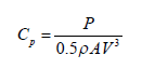
This is the maximum fraction of power extraction possible from the ambient wind and is required only when the 1-Simple Simulation method is selected. This value can be calculated from the power curve published in most manufacturers' specifications by using the kinetic energy equation as:
where:
P = power production at the rated wind speed [W] ? = density of air [kg/m3] A = swept area of rotor [m2] V = rated wind speed [m/s] Cp = power coefficient
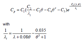
The maximum and default coefficient values are 0.59 and 0.35 respectively. Annual local average wind speed This is the local annual average wind speed that represents a representative wind profile at the location of the system (in m/s or ft/min). It is used to factor the difference in wind speed between the weather file wind data and the locally measured wind data so that the model minimizes uncertainties caused by improper wind data at the particular location. Considerable differences between the weather file wind data and the local wind data typically appear so it is important to consider this carefully in order to use accurate local wind data in the simulation. The model internally determines a multiplier and it is multiplied by the weather file wind data adjusted at the height of the system. Height for local average wind speed This is the height that the local wind speed is measured (in m or ft). The annual average wind speed (see previous field) input by the user is internally recalculated by existing EnergyPlus functions at the height of the local station. This modified wind speed is then factored and applied to the weather file wind data. The minimum and default values are zero and 50m. VERTICAL AXIS For vertical axis turbines you can enter details on the Blade chord area, drag coefficient and lift coefficient on the Vertical Axis tab. Blade chord area This is the blade chord area of a single blade of VAWT system in (m2 or ft2). It is necessary to determine the net tangential and normal forces of a single blade. Blade drag coefficient This is the blade drag coefficient for a specific blade. It is for determining the tangential and normal force coefficients with the blade lift coefficient (below) so that the model can calculate the power output from the system. The user should be able to obtain this parameter for a specific blade from the manufacturers’ data. This field is only required for VAWT systems. Blade lift coefficient This field is the blade lift coefficient for a specific blade. It is for determining the tangential and normal force coefficients with the blade drag coefficient (above) so that the model can calculate the power output from the system. The user should also be able to obtain it for a specific blade from the manufacturers’ data. This field is only required for VAWT systems. For horizontal axis turbines using the 2-Analytical Power calculation method the Power coefficients can be entered on the Power Coefficients tab. Power coefficient parameters C1-C6 These six fields are the parameters for the power coefficient equation shown below. These fields are used to determine the power coefficient of the system. The analytical approximation model of the power coefficient in EnergyPlus is:
where:
Cp = power coefficient C1- 6 = empirical power coefficient parameters ? = tip speed ratio (often known as TSR) ?i = tip speed ratio at ith time step ? = azimuth angle of the pitch, 0 [degree]
The default values are given in the table below.
|