Poste de distribution Electrique


|
Poste de distribution Electrique |
|
|
Electric load centres are components used to include on-site electricity generators in a simulation. The electric load centre dispatches generators according to operation schemes and tracks and reports the amount of electricity generated and purchased. When using on-site generators, the program provides a “net” report where the total electricity used is reduced by the amount generated on site. Electrical demand tracking is done by the internal or custom meters used by EnergyPlus for reporting. The dispatching of different generators is based on expectations based on their nominal/rated electric power output. If the current conditions are such that the generator model determines that generation was higher or lower, then the results of the dispatch may differ from expectations.
Up to 5 different Electric load centre components can be included in simulations by making selections on the On Site Electricity Generation tab. A great deal of flexibility is available by mixing different load centres and operating schemes. If multiple load centres are used, the supervisory control will dispatch generators sequentially across the load centres.
Electric load centres effectively serve as a “load” to the generators and “supply” power to the rest of the building. The internal meters used by EnergyPlus for reporting do all of the demand tracking. The electric load centre manager sums all of the building and system electric loads and provides operating schemes for the generators. What is not provided by the on-site generation equipment, and electric storage units if specified, is met by (purchasing) off-site electricity.
The electricity produced from photovoltaic arrays is reported in the electricity produced output variable and will reduce the demand that the generators will try to meet for that timestep.
Load centres can include both power conditioning and storage. Separate inverter models are used to condition DC power from photovoltaic panels into AC power for the building and utility. Load centres serving PV need to be specified with a direct current (d.c.) buss. The other generators may have inverters inside the devices but these are already embedded in the generator models. GENERAL Name This alpha field contains the identifying name for the electric load centre. Generator operation scheme type Select the type of operating scheme for the generator set. The various operating schemes affect how loads are dispatched to the generators, in effect telling the generators whether or not to run and requesting power levels. The available operating schemes are:
The 2-Demand limit, 3-Track electrical and 4-Track schedule schemes will sequentially load the available generators. All demand not met by available generator capacity will be met by purchased electrical. Therefore, if 2-Demand limit, 3-Track electrical, or 4-Track schedule is used and the available generators are not able to meet demand, then purchased electricity will by used to offset the difference. If a generator is needed in the simulation for a small load and it is less than the minimum part load ratio the generator will operate at the minimum part load ratio and the excess will either reduce demand or the excess energy will be available for returning to the electric grid.
If the load centre includes electrical storage, then the choice of operating schemes will also affect how storage is managed.
For all operating schemes except 1-Baseload, a total electric load reduction target (or thermal load converted to electrical equivalent) is established for the load centre based on the specific operating scheme. The load centre then requests that its generators operate, one-by-one in the order specified, until the target is met or exceeded. Generators that are not scheduled as ‘available’ for the simulation time step are not called to operate. The requested power demand to be met by each generator is the smaller of the nominal ‘rated’ electric power output (as specified in the Generators object) or the remaining total electric load reduction target for the load centre. After each electric generator is requested to operate, the actual electric power delivered by the generator, which may be greater than or less than the requested amount due to inputs specified in the generator performance model, is used to update the remaining total electric power target for the other generators associated with this load centre. Most of the operating schemes will sequentially load the available electric load centres and generators. EnergyPlus can accept multiple Electric load centres with different operating schemes. Because of this, there are two levels of reporting, one for the whole building and a second for each load centre. The whole-building results are managed with the internal meters for the entire model. The individual load-centre results are summed for those generators connected to a particular load centre. The total electricity purchased is reported both in power and energy units. This value is positive when the amount of energy is purchased from the utility. This value can be negative when the total electricity produced is greater than the facility electrical needs. The excess will either be available for storage or to sell back to the electric utility company. Demand Limit Scheme Purchased Electric Demand Limit The demand limit above which the generators will try and meet the entire electrical load on the building minus the photovoltaic array if available (in W). Track schedule When the 4-Track schedule option is used then you should select a schedule containing values for the “demand” loads placed on the generator(s). The schedule values should be in Watts. This alpha field is used to describe how the electric load centre is configured with respect to any power conditioning and/or storage equipment. There are five configurations for load centres available by using one of these keywords:
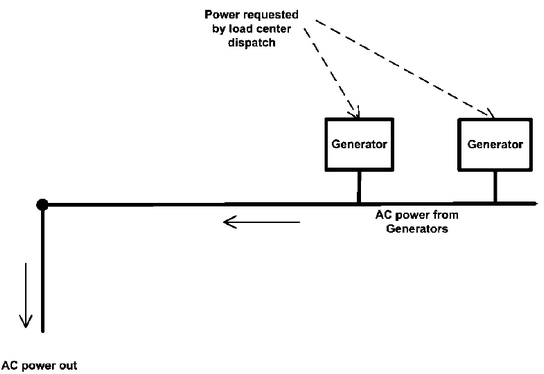
All the generators connected to a specific load centre need to be of the same type (all AC or all DC). If the generators are DC, then an inverter is needed to convert the DC to AC. The most basic configuration is selected with the keyword “Alternating Current” for the Electrical Buss Type, shown in the following diagram.
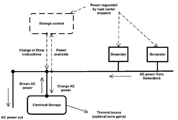
The Alternating current load centres have AC generators with no storage and behave in the following way. All electric demand not met by the sum of the electrical power produced by the available generators will be met by purchased electricity. If a generator is needed in the simulation for a small load and the load is less than the generator’s minimum part load ratio, the generator will operate at the minimum part load ratio and the excess will either reduce demand or the excess energy will be exported back to the electric utility company. The purchased electrical demand limit is the user input for the demand limit above which the generators will try and meet the entire electrical load on the building. It is possible to prescribe a set of ElectricLoadCenter:Distribution objects with inconsistent or conflicting operating schemes, so users need to be careful. Alternating current with storage A configuration with AC generators with on-site electrical storage is selected using the 2-Alternating current with storage Electrical buss type and is shown in the following diagram.
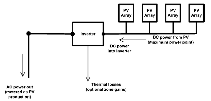
The Alternating current with storage load centres attempt to augment the generator electricity production so that the power requests are met. Storage control logic is discussed below under Electrical Storage. The basic configuration for photovoltaic generators is selected using the 3-Direct current with inverter electrical buss type and is shown in the following diagram.
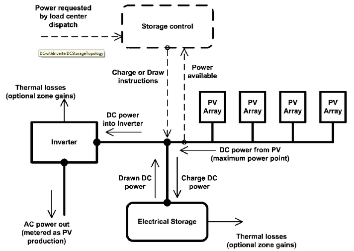
The Direct current with inverter load centres collect DC power from various PV arrays, run the DC power through an inverter and produce AC power. The PV arrays produce DC power based on the availability of sunshine and do not respond to load requests made by the electric load centre. The AC output from the inverter is what is recorded as electricity production. Direct current with inverter DC storage If the PV-based load centre is equipped with DC electrical storage that is connected before the inverter, then the buss type should be 4-Direct current with inverter DC Storage and is shown in the following diagram.
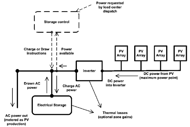
The Direct current with inverter DC storage load centres charge or draw DC power to meet the requested electrical load. Direct current with inverter AC storage If the PV-based load centre is equipped with AC electrical storage that is connected after the inverter, then the buss type should be 5-Direct current with inverter AC storage and is shown in the following diagram.
The inverter selection option is only used if the Electrical buss type is set to 3-Direct current with inverter and it allows you to select the inverter connected to this load centre (if any). There are three types of inverter models available:
The storage selection option is used to identify the electrical storage connected to this load centre (if any). It is only used if the Electrical Buss Type is set to 4-Direct current with inverter DC storage or 5-Direct current with inverter AC storage. COST Distribution and electrical cost Enter the cost of the electrical power distribution and any other related costs here.
The cost of the panels themselves is entered on the Constructions tab under the Solar Collectors header. On the Generator List tab you can define up to 30 generators per Electric load centre. Set the number of generators and select the generator to be used for each. For DC Electric load centres the generators will all be PV solar collectors and for AC centres the generators will all be Wind turbines.
|