Matériaux à changement de phase


|
Matériaux à changement de phase |
|
|
Phase Change tab on Materials Dialog.
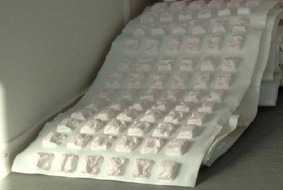
Phase Change Materials (PCMs) are often impregnated into gypsum board, plaster, concrete or other materials in order to increase the thermal storage capacity of ceilings, walls and floors. Some PCM manufactures also provide mats of pure PCM "pockets" which can be included as layers within constructions.
Example of PCM Mat
By completing a transition between solid and liquid phases PCMs can absorb large quantities of latent heat. The high latent heat storage capacity of these materials works to effectively increase thermal mass which tends to moderate interior temperatures and improve comfort conditions. PCMs are frequently used to reduce the need for mechanical cooling, peak load shifting and improving solar energy utilisation.
DesignBuilder allows you to enter manufacturers phase change properties in the form of a temperature - enthalpy curve on the Phase change tab of the Materials dialog. Some default PCMs are provided with the materials database that comes with DesignBuilder. PHASE CHANGE PROPERTIES Phase change material When the Phase change material check box is selected, this material is simulated as having the following temperature dependent material properties. Temperature coefficient for thermal conductivity This field is used to enter the temperature dependent coefficient for thermal conductivity of the material. Units for this parameter are W/m-K2. This is the thermal conductivity change per unit temperature excursion from 20°C. The conductivity value at 20°C is the one specified with the basic material properties of the regular material specified in the name field. The thermal conductivity is obtained from:
k = ko + k1(Ti - 20)
where:
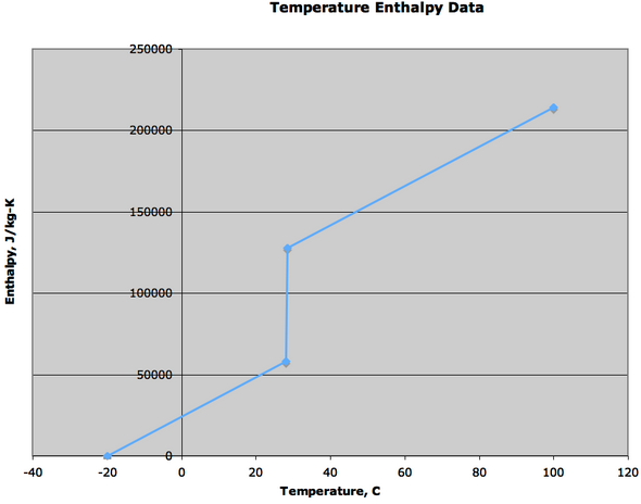
ko is the 20°C value of Thermal conductivity entered on the Material properties tab of the Materials dialog. k1 is the change in conductivity per degree temperature difference from 20°C (this field). TEMPERATURE-ENTHALPY CURVES The temperature – enthalpy set of inputs specify a two column tabular temperature-enthalpy function for the basic material. Sixteen pairs can be specified. Specify only the number of pairs necessary. The tabular function must cover the entire temperature range that will be seen by the material in the simulation. It is suggested that the function start at a low temperature (-20°C is typical), and extend to 100°C. Note that the function has no negative slopes and the lowest slope that will occur is the base material specific heat. Enthalpy contributions of the phase change are always added to the enthalpy that would result from a constant specific heat base material. Examples of simple generic enthalpy temperature function and also manufacturers data is shown below.
Generic Data from EnergyPlus
Example of Manufacturers PCM Data
Number of points on the curve Select a number from 1 to 16. The number of points selected here will determine the number of points available for data entry below. Temperature x This field is used to specify the temperature of the temperature-enthalpy function for the material. Units are °C or °F. Enthalpy x This field specifies the enthalpy that corresponds to the previous temperature of the temperature-enthalpy function. Units are J/kg or Btu/lb. SOLUTION ALGORITHM
Important note: The Finite Difference solution algorithm must be used to include the effect of material phase change properties in simulations. If you instead use the CTF algorithm the material will behave as if its PCM option were not selected. Note also that the CTF solution algorithm is the only option available for Heating and Cooling design so the phase change effect of the material will not be seen in these calculations. An error message to this effect will be generated for PCM simulations where the CTF solution method is selected. Tip: With Learning mode active, the Info panel for the Phase change tab includes a link to load a set of default simulation properties recommended for PCM analyses.
|